Case Study: Heat Transfer (OHTC) x Vortex Induced Vibration (VIV)
Ice, Ice, Baby
Alright stop, collaborate and listen…
Aside from his foundational work to establish what became the first law of thermodynamics, James Joule’s work on expansion cooling of real gases has been known since the 1850’s (primarily related to localized throttling devices). Within the oil/gas industry, we observe these effects, both locally and manifested over longer distances (pipelines) with changes in process conditions.
In some early deepwater (gas) developments, temperatures were observed to be much colder than expected. The initial expectation was that temperatures should mimic the surrounding environment (ambient seawater) for these bare steel risers…but that was not the case. Could that be attributed to Joule’s work? Or is there something else at play?
Understanding expected operating conditions has a big impact on both process design and operating efficiency. We take a deeper look into those factors in this case study, also referencing a widely-known paper that shows the effect of vortex-induced vibration (VIV) mitigation, and how that may play a role thermally.
Joule-Thomson Effect
The Joule-Thomson (JT) effect can be most simply described as the temperature change undergone by a real gas as it expands. Depending on pressure, this process can induce a warming (JT-Heating, high pressure ) or a cooling (JT-Cooling, low pressure) effect, largely driven by the slope of the enthalpy curve. The cooling effect (low pressure) is often exploited in refrigeration processes by allowing gas to expand through a throttling device (i.e. valve). To see this, simply breathe in with your lips pursed and you can observe this cooling effect in action.
On a more detailed level, the JT effect can be represented by the change in temperature/pressure through lines of constant enthalpy. Taking the gas below (natural gas, mostly methane) and considering an isenthalpic expansion, one can fairly easily predict the resulting temperature that occurs with a drop in pressure.
Initial Condition: 2000 psi / 40°F
Final Condition: 1000 psi / -10°F
It can also be observed that the slope of the enthalpy lines becomes steeper at lower pressures. In a practical sense, this means the change in temperature (for the same DP/psi change) becomes increasingly more dramatic at lower pressures.
These calculations are most applicable to short (and adiabatic) areas such as valves/orifices, where the effect of the fluid changes can be isolated. In real hydrocarbon systems, the change in temperature is seen acutely across valves, but more gradually across pipelines as the fluids move from high pressure to low pressure over a large distance/surface area. In these more ‘macro’ environments, temperature changes are impacted by several factors:
Heat addition due to work (pump, friction, etc.)
Heat loss to surroundings (U-value / overall heat transfer coefficient)
Heat loss due to potential energy changes (lifting fluids from reservoir to surface)
Heat loss due to internal fluid changes (JT Effect)
In most systems, the two primary factors are (a) loss to environment and (b) internal fluid changes, with potential energy being a more dominant factor in deepwater oil systems due to the greater hydrostatic head component. We will discuss the implications of these in later sections. SPE-71545 does a much better and more detailed job discussing the components of heat transfer (with equations), but a synopsis of the findings is shown below.
FIV vs. VIV
Now that the party is jumpin'…
We spoke in the past about the impact of internal fluid flow on physical structures and the potential to induce vibrations via the fluids’ kinetic energy, particularly around geometry changes (i.e. bends). This is commonly referred to as ‘Flow Induced Vibration’ (FIV).
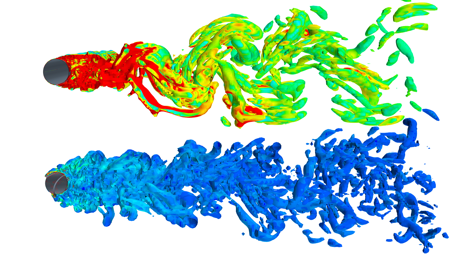
Similar issues may arise when considering external fluid flow across structures. A classic fluid dynamics problem considers fluid flowing across a cylinder and the resulting impact on movement. The fluid slows as it moves across the body, but upon exit from the viscous boundary layer, vortices are formed and may impose motion on the body (as shown below)
Similar to FIV, these ‘Vortex Induced Vibrations’ (VIV) can lead to physical damage to the structure/body, which may manifest in catastrophic failure or a gradual reduction in fatigue life. As such, mitigation measures are considered to either change the geometry of the structure or - more likely - change the flow pattern around the structure to change these eddy currents and reduce the VIV impact.
VIV Mitigation Methods (Strakes vs. Fairings)
Keep my composure when it's time to get loose…
In an effort to mitigate the effects of vortex induced vibrations (VIV), there are typically two physical options that adhere to the outside of the pipe:
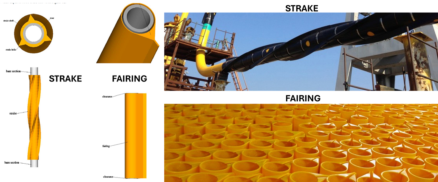
Strakes: External helical fins that wrap around the outside of the pipe
Fairings: Free-rotating fins that self-orient in the direction of current flow
As a result of the physical configuration, they each result in two different wake patterns behind the pipe (indicatively shown below). When considering construction (adherence to pipe, weight, etc.) and the resulting vortices, an estimate can be made on coverage length required to effectively reduce any VIV-related fatigue damage.
The selection of VIV mitigation (type + length of coverage) can readily be calculated to achieve a desired fatigue life. Excluding cost, additional factors are considered in the selection of the appropriate solution:
Marine Growth Challenges: Strakes are somewhat more susceptible to marine growth, relative to fairings.
Installation Challenges: Fairings have a more complicated configuration to attach to the pipe and install. Aside from the need to be free-moving, additional components (i.e. thrust collars) pose challenges particular for S-lay installation means
Thermal Challenges: Each option has a different heat transfer profile, based on (a) physical material/coverage on the pipeline and (b) any localized ‘stagnant’ water layers near the outer pipe wall that provide some level of thermal resistance. The resulting conduction (material) and convection (near-surface currents) give different overall heat transfer (OHTC, U-value) profiles for each VIV option.
For a highly insulated pipeline, the net effect of the VIV suppression mechanism is minimal. The primary resistance terms are the actual insulation materials themselves and the VIV suppression mechanism adds little. However, for an un-insulated pipeline (i.e. “bare steel”), the VIV suppression becomes the dominant source of thermal resistance and ultimately controls the heat transfer in the pipeline. As such, the VIV solution must be considered when evaluating the system’s thermal performance. Traditionally, these are de-coupled during early engineering efforts.
And it is in this scenario (deepwater gas + un-insulated riser + VIV) where the story takes a turn…
VIV Solution: Impact on U-value
If there was a problem, yo, I'll solve it…
Calculation of the overall heat transfer coefficient (OHTC, U-value) for complex geometries requires a rigorous, computational fluid dynamics (CFD) assessment, primarily to obtain the external heat transfer coefficient induced by the water convection. In this case, CFD assessments were carried out by Element Digital Engineering on both strake and fairing concepts, highlighted below, to assess both current/wake patterns and resulting thermal behavior.
Overall heat transfer coefficients were determined by considering the resistances for:
Internal fluid convection (hi)
Material conduction
External fluid conduction + convection (ho)
Typically, the external heat transfer term (ho) is high and can be ignored. But in this case, it must be rigorously calculated to quantify the effects of the VIV suppression over the complex geometry, which results in a much more pronounced component (as compared to convection across a bare cylinder)
In this scenario, the U-values are estimated to be as-follows:
Bare Pipe (No VIV): ~200 W/m2-K
Fairings: 50 W/m2-K
Strakes: 15 W/m2-K
Values are obviously case-specific, but are reasonable indications of the variance across the different VIV mitigation options. Consideration may be given to augmenting the physical configuration of the strake/fairing to expose more area to encourage more heat transfer, but this could open re-qualification efforts to ensure VIV suppression remains as-designed, as well as ability to manufacture/install the “new” design.
In many systems, low U-values are a good thing. We pay a lot of money to enable heat retention and keep fluids hot to avoid solids deposition (i.e. paraffin) or arrive above hydrate conditions. However, in a scenario where the fluid is undergoing a large amount of JT-cooling, the low U-value actually inhibits heat transfer with the “warmer” seawater, essentially trapping the cold temperature in the fluid. As such, the more insulating effects…the potential for colder fluids.
U-Value: Impact on arrival temperature
Quick to the point, to the point, no fakin'…
Estimation of arrival temperature is generally governed by two factors:
Joule-Thomson Effect (JT cooling), as the pressure drops
Heat transfer with surroundings, including variations in ambient temperature and current velocity vertically up through the water column
Referring to the enthalpy plot at the outset, a gas moving from high pressure (seafloor) to low pressure (surface) could experience >50°F change (drop). This is counter-acted with a warmer ambient seawater, whereby the outside fluid is ‘heating’ the colder gas as it ascends the riser. Without rapid heat transfer, the gas temperature is not able to equilibrate and will arrive much colder.
Ignoring any insulation effects for a moment…
At low flowrates, the gas has adequate residence time to equilibrate with the warmer surroundings, providing an upper-bound (“ambient”)
At high flowrates, the gas undergoes the full effect of the expansion cooling, proving a lower-bound (“JT effect”)
As a result, the actual flowing temperature could be anywhere in-between, based on flowrate and (now) the rate of heat transfer with the surroundings
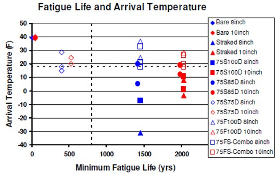
Looking at VIV suppression (fairing vs. strake) as a function of (a) operating pressure and (b) gas flowrate, we see a stark contrast in arrival temperatures between the two configurations, as dictated by the effective heat transfer coefficient of each.
Of note, this is a similar trend shown in one of the earliest published papers on the topic (OMAE2006-92575, “Coupled VIV and Heat Transfer”), both the temperature profiles, as well as the various effects of each mitigation option (Fairing - F, Strake - S).
Further complicating the heat transfer assessment is the fact that VIV is typically an issue in the upper water column only, where the seawater currents are highest. As such, the VIV suppression need only be applied to those shallow water depths (<1000m)…but this is precisely the area where the ambient seawater temperature is the warmest and where rapid heat transfer with the ambient is preferred.
Solution: Coupled VIV / Heat Transfer
Conducted and formed, this a hell of a concept…
As an old colleague used to often say, “So now what?” We can calculate how much VIV suppression is needed (and where)….we can calculate the U-value (even if its hard/complex)… and we can calculate the arrival temperature…so, problem solved, right? Well, no.
Temperature can be manipulated by taking less pressure drop (less JT cooling effect), but this comes at the expense of production back-out due to higher back-pressure on wells.
If the arrival temperature is too hot, it impacts potential gas dehydration technology (JT vs. TEG, etc.)
If the arrival temperature is too cold, it impacts metallurgy (i.e. flex joint limits) and hydrate mitigation strategy. Requirements for MeOH / MEG rapidly increase for every incremental drop in temperature, potentially adding $MM’s in CAPEX for large MEG units.
Ok, no problem, we understand the heat transfer side of the equation. We can begin to tailor the thermal behavior by adjusting our U-value (i.e. strakes / fairing option and coverage length) to manipulate the temperature problem. Just use less.
However, we are brought back full-circle to the reason why consider strakes / fairing configurations in the first place: managing VIV and the resulting fatigue life. Reducing the VIV coverage may result in warmer temperatures…but may also fail to meet fatigue life requirements.
We often find ourselves in a Goldilocks scenario where we need to be “not too hot, but not too cold”…and also find a design that is installable and effective over field life.
Closing Thoughts
Ice, ice, baby (too cold, too cold)…
As we are fighting physics in most cases, the solution often tends to drive temperatures colder while effectively managing VIV / fatigue life.
This is a solvable problem…as long as you know what to look for. Having a ‘systems-level’ approach and understanding the drivers of each discipline early in the design helps ensure the greatest chance of finding a technically-feasible and economically-viable solution. Which, if known up-front (before production), can be more easily accommodated.
PS: Maybe Vanilla Ice really knew something about flow assurance. After all, his lyrics contain “ice”, “chemical” and “wax”…hmmm…


