Thirst Traps and SuperTRAPP
LDHI Alternatives to MEG for Lean Gas Developments
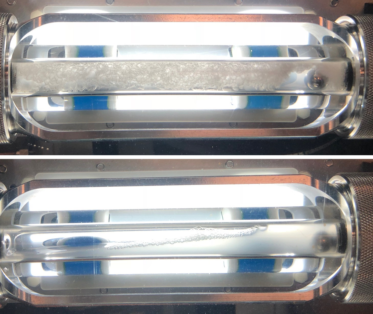
When done correctly, chemistry tells a beautiful story through pictures. #nofilter.
In this week’s installment of Data and Discipline, we tackle a challenge that the offshore industry has dealt with for many years and hope to shed some light on the decision-making process that goes into some critical field development decisions: treating hydrates in deepwater gas developments.
Hydrate Management 101: MEG
In most offshore developments, the list of hydrate control options is pretty standard and is something most flow assurance engineers / production chemists know well:
Thermodynamic Inhibitors
Methanol (MeOH)
Mono-ethylene Glycol (MEG)
Low Dosage Hydrate Inhibitors (LDHI):
Kinetic Hydrate Inhibitors (KHI)
Anti-Agglomerants (AA)
Non-Chemical Alternatives
Active Electrical Heating (AEH)
Heated Pipe Bundles
Cold Flow
The intent of this post is not to go into the pros/cons on each of these. In most cases, the leading candidate tends to be MEG (Mono-Ethylene Glycol). Field-proven, non-contaminating, robust to fluid properties, low commodity cost (OPEX), environmentally friendly, recyclable and ease of supply chain / logistics make MEG a good option for most developments. MEG is regenerated topsides (water boiled off) and regenerated (cleaned of any produced water/salts) before being re-injected, largely as a closed-loop system.
However, it comes at a price…literally. MEG requires an up-front CAPEX investment, typically in excess of $50MM USD. Adding to this, the MEG unit must be sized for a known produced water volume. In my years dealing with reservoir models and water prediction, I have learned one thing - they are almost always wrong. Too much water and the MEG unit is undersized. Too little water and we pre-invested too much CAPEX. So, chasing the “Goldilocks” solution of just the right amount is indeed often a fairy tale.
Alternatives to MEG
In this case study, we evaluate a very specific alternative to MEG: the Low Dosage Hydrate Inhibitor, Anti-Agglomerant (LDHI-AA). Similar to MEG, AA would be injected continuously at the wellhead to control hydrates, ideally through umbilical tubes (vs. a separate “MEG Pipeline”). Unlike MEG - which is largely a closed-looped system - the AA is assumed to be a once-through chemical that must be continuously re-supplied. However, the dosage volumes are much less, up to 100X lower (1:1 MEG:Water vs. 0.01:1 AA:Water)
For all of the fans of other options, you will get your day in court on a subsequent case study. Let’s just say they didn’t meet the criteria for this ultra-deepwater, ultra-long distance tieback. Too much sub-cooling and too much residence time. That should put Team LDHI-KHI and Team Active Heating on the sidelines for the rest of this article.
Also, Pete Conrad and I co-wrote a paper about this very topic for the Offshore Technology Conference (OTC), so nothing like recycling some of our points.
How Do Anti-Agglomerants (AA) Work?
Unlike MEG, AA’s work on the flow stream by NOT preventing hydrates. Makes perfect sense, right? While it may sound counterintuitive that AA’s do not prevent hydrates from forming, the mechanism by which AA’s operate is based on being crystal growth modifiers. This allows the hydrate particles to form as small, needle-like crystals, making them much easier to disperse into the oil phase and less likely to agglomerate. This is turn results in a transportable hydrate slurry. Ideally.
Structurally, AA’s are generally small organic molecules with surface-active properties containing a hydrophilic, polar head which fits within the hydrate crystal as it grows and a hydrophobic aliphatic chain. As hydrates are formed, the polar head associates with the polar surface of the clathrate hydrate structure and will disperse the hydrates into the oil phase, resulting in a flowable slurry. While not necessarily emulsifying, AA’s will make the brine more dispersible in the liquid hydrocarbon phase.
One differentiating feature between available chemistries in the marketplace is in keeping the hydrate particles as small as possible, which improves dispersibility and minimizes the potential to form larger and larger agglomerates. The latter occurs when larger hydrate particles are formed as a hydrate shell encapsulating free water. Free water is released through various collisions and becomes available to fuse to other agglomerates through hydrate growth, resulting in larger structures that are more prone to blockage. This is what the AA prevents from happening.
Field Performance Criteria:
Given that AA’s work as dispersants and rely on slurry transportation, there are several key fluid property criteria that must be achieved to confidently allow consideration for use. The two main (high-level) screening criteria that are most often used are:
Overall liquid fraction: Maintaining adequate liquid holdup fraction in the pipeline to allow hydrate slurry dispersion and transportation. While there is no specific criteria, since the performance limit is based on the actual liquid properties, typical numbers are >5% liquids. This can be supported with multiphase flow modelling to evaluate liquid drop-out along the pipeline, as well as laboratory testing to confirm actual liquid limits.
Water Cut: Similar to above, the total amount of hydrate slurry formed must be transportable within the liquid phase. As water production increases, the amount of hydrate slurry also would increase. This makes AA usage more challenging in keeping a manageable level of hydrate conversion. Increased AA dosages may be required, but there is a practical limit to how much hydrate can be tolerated and transported. Maintaining this ratio (hydrates / liquid phase) is key, again with typical values of <50% water cut.
Both of these values are project-specific and fluid-specific, but often form the initial basis for AA feasibility assessment. It should be noted that most applications for AA’s are for oil-dominated systems. Liquid holdup fraction is generally not a concern, so only the water cut limit may pose a challenge. However, for gas-dominated systems, the minimum liquid fraction quickly becomes the biggest challenge.
Other considerations, such as recirculating condensate to maintain sufficient liquid fraction and/or minimize control water cut may be necessary to achieve the requisite phase behavior. However, these add complexity and cost, which are counter to the simplicity of the LDHI option, and thus were not actively progressed at this stage.
Fluid Sampling Challenges: Accurate Condensate/Gas Ratio (CGR)
Given that one of the criteria is liquid fraction, accurate prediction of the liquid yield and associated phase behavior is obviously a key component. In particular, lower liquid yield systems (lower CGRs) have an inherent challenge in measuring the actual phase behavior. What makes it extremely difficult to accurately measure is the extremely small volumes of liquid involved, particularly in the absence of a welltest (drill stem test, DST) or flowback.
For example, if you have a 500cc gas collected (typical downhole sample cylinder size) and the CGR is <5 bbl/ MMscf, this equates to a volume of condensate <0.014 ml, which with the equipment available, will be very difficult to measure accurately. This is likely to introduce significant error into the calculation.
Even if you are able to weigh (vs. measure) this small amount of condensate in a very sensitive mass balance, the problem is that you are unlikely to know the actual density of the condensate that has dropped out of the gas phase. So, the density of the condensate must be estimated, which just adds error-on-error. Finally, to counteract the small condensate volumes, it requires much larger volumes of gas sample to be taken and in most instance this is just not economically feasible.
For higher CGRs, the errors are less of an issue (+/- 2 bbl/MMscf for a 20 CGR fluid is only 10%). However, +/- 2 bbl/MMscf for a 5 CGR fluid is 40% AND may make the difference between an AA option being effective or not.
Further complicating the CGR measurement is the potential changes over time with reservoir depletion. Condensate banking / reservoir leaning over time may allow consideration for a given hydrate management strategy initially, but changes in fluid properties over time may not offer a robust option for life-of-field when considering LDHI-AA’s. More conventional approaches (i.e. MEG) are much more robust to changes in fluid properties.
Significant work has been done within the industry for low liquid holdup systems, particularly by Schlumberger and Sintef (et. al.) to improve liquid holdup and and pressure drop predictions in multiphase flow models. However, the inherent uncertainties with the base measurements of liquid yield remain.
Water Salinity Challenges: How Clean is Too Clean?
AA chemistries are known to be performance-dependent on the salinity of the brine. When the Total Dissolved Solids (TDS) are <35,000 mg/L , the required dose rate of an AA has been shown to increase dramatically. Salt is a known thermodynamic hydrate inhibitor, but if AA’s allow hydrates to form, why does this matter?
One consideration is in the changing salinity of a system as hydrates are formed. Hydrate structures do not incorporate salts, so if 50% of the water is converted to hydrates then the remaining aqueous phase salinity is doubled. This was illustrated in OTC2895MS, where several rocking cell tests found systems became self-inhibiting between 170,000 – 220,000 mg/L TDS, depending on the liquid phase.
Another factor that has been explored involves the AA’s ability to disrupt the interfacial tension between oil and water. Obviously, changing the salinity and density of the aqueous phase alters this, and lower saline systems present a more challenging environment for the chemistry. In addition, the increase in salinity may improve the adsorption of the AA chemical onto the hydrate structure and impact the overall solubility of the molecule. Thus impacting its ability to maintain itself at the liquid hydrocarbon / water interface.
All of these considerations are important, particularly in a gas-dominated system, where condensed water for some or most of the field life is typical. There have been reported applications of AA’s in fresh water / condensed systems, however other factors in the system profile and design have made these the exception rather than the norm for hydrate mitigation strategies. Adding to the challenge is that the water salinity is likely to change over time. Initially, low salinity condensed water dominates, transitioning to higher-salinity formation water over time.
Case Study: Remote Gas Reservoir
For this specific scenario evaluating alternatives to MEG, the project economics were marginal and likely would not support a local host concept. So, a subsea tieback was considered, with a focus on a low CAPEX solution that could assume some incremental risk. One of the largest cost levers was an alternative to MEG for the hydrate management strategy.
Unfortunately, this low CGR system was challenged on both the minimum liquid holdup fraction AND the water cut over time. Data below shows liquid holdup fraction and water cut, both of which are either below our “rules-of-thumb” or borderline for a large portion of the field life. As noted at the outset, the efficacy of the AA is driven by the actual liquid properties , so there may be opportunity to consider applications even when the screening-level criteria are marginal.
One additional benefit of an AA application (vs. MEG) would be the ability to prevent significant liquid hold-up in two areas:
Elimination of high-density / high-viscosity MEG, which will preferentially hold up in the pipeline and increase back-pressure.
Stop water dropping out as a separate phase due to the AA dispersion properties, this transporting everything as a mixed condensate/water phase.
Both of these will serve to reduce back-pressure on the wells for an AA application, potentially decreasing the abandonment pressure of the reservoir and thus increasing EUR (Estimated Ultimate Recovery).
How Low Can You Go? Examining Low Liquids in Rocking Cells
Rocking cells are one of the most widely-used instruments in laboratory hydrate studies. Depending on the units, multiple tests can be carried out to screen variables quickly, including LDHI types / dosages / water cuts, etc. Also, one other advantage of the rocking cells is their low fluid volume requirements, which are often critically important when there are a lack of production fluids. This is especially important for low CGR fluids, where condensate is at a premium.
The rocking cell is typically ~45 cc total volume and often times cells are 50% liquid-loaded, which means each test does not consume much oil. They are robust, typically have visual capabilities, and because they are low shear tests are good for conservative estimates with AA efficacy. To put it simply, one can literally see the chemistry work, and if a chemical works in the rocking cell there is high confidence it will work in the field. The low shear is generated by tilting the cells back and forth allowing a steel ball inside the cell to travel from one end to the other by gravity as the only force moving the ball.
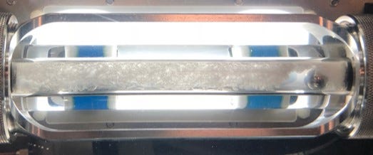
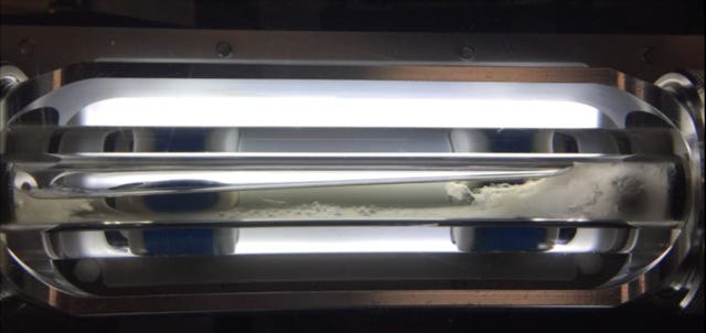
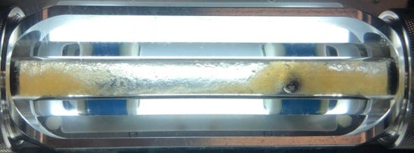
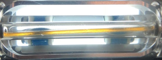
Sapphire Rocking Cells (PSL Systemtechnik, Germany) shown below.
An obvious failure occurs when the cell turns into a hydrate popsicle with the ball stuck inside.
Early method development in rocking cells settled on 50% liquid loading to ensure hydrate formation was not gas-limited, and each test, theoretically, could have complete conversion of water into hydrates. Recent interest in AA technology for gas-dominated systems have caused us to (re)ask what are the minimum volume requirements we can examine hydrate plugging in a rocking cell? There are unfortunate examples of gas-dominated systems that have experienced hydrate incidents in the field. It is not hard to imagine a plugged flowline with an “infinite” supply of water to feed into a hydrate plug! To try and replicate this effect, flow loop testing has attempted to remelt any hydrates formed at the end of the loop, so that there were always fresh hydrates arriving in the cold part of the loop. This demonstrated even in very low water cut systems (<5%), over time a hydrate plug could form as long as water continues to seed the cold gas
In a rocking cell, there is a minimum volume of water needed to form a hydrate plug, which is defined - in this case - as being able to stop the moving ball and register a failure. In standard 50% liquid loading tests, we are able to observe hydrate plugs in a minimum 10% water cut scenario. In a 45-cc cell this equates to 2.25 ml brine volume.
Viscosity Challenges
Perhaps not so obvious to analyze is a system with hydrates well-dispersed into the liquid hydrocarbon phase resulting in a viscous slurry. While one can clearly visualize a hydrate plug is not present, the fluids are viscous and the ball remains suspended and/or moves slowly along the tube before the cell is rotated back. One may be tempted to consider the lack of a hydrate plug a “Pass”; however, a viscous slurry several miles long will require tremendous energy to produce. And would that be an acceptable risk for a long-distance, remote subsea pipeline?
Flow loop work by a major operator indicated that at water cuts >50%, the viscosity of the resultant slurry became hydraulically-limiting. Therefore, even though it may be possible for an AA to work at water cuts up to 80% water cut, the resultant slurry is likely to be too viscous to flow under natural conditions. Even at water cuts <50%, this increase in system back pressure due to slurry viscosity may reduce significantly the ultimate recovery of any gas reservoir. This is likely where real value erosion will occur. This isn’t an issue for oil-dominated systems because the effect is a short-lived transient, but for gas-dominated systems operating continuously in the hydrate region, this viscosity issue can be the biggest fundamental risk.
Likewise, there is a minimum volume fraction of condensate required to transport a hydrate slurry (think of all the smoothies you’ve tried to make in your Ninja Bullet that you can’t pour out). To date, there is not an established threshold CGR (condensate/gas ratio), a system must operate in to consider AA chemistry. This is new frontier question we are asking and hoping to address (partially, at least) in the rocking cell. Stay tuned for more updates on this one…didn’t think we would give away the answer in one post, did you?
And…maybe most important…how reliable are these volumes (2 ml of condensate) in accurate predicting ‘scale-up’ to full-flow production in large diameter pipelines? Scale up of the test results, particularly for a novel test at such low liquid loadings, may present the most onerous challenge of all. If we see the tests “Pass” in the rocking cells, will those pass in the field?
Other Considerations: Environmental Profile
AA’s have most applications in Gulf of Mexico, where unplanned shut-ins and small volume requirements vs. thermodynamic inhibitor counterparts make them advantageous. They have not been accepted in other regions, such as the North Sea, due to their historically poor environmental profile. 1st generation AA’s were quaternary amine salts (“quats”), which have unacceptable toxicity, biodegradation and bioaccumulation numbers.
Most chemical supply companies have gone away from the quats, and there are reports of improved profiles. However, the AA stigma in the North Sea has thus far prevented serious consideration in the region. Part of the challenge resides in the classification of the chemistry and the field dose levels. First, as the active component is a surface-active chemical and technically considered a surfactant in the required environmental testing profile, the exposure requirements in toxicity testing are not allowed to consider partitioning benefits. So, the primary consideration for its use is based upon the toxicity of the entire field dose rate, with secondary consideration made to its biodegradation and bioaccumulation trends to determine its overall environmental impact. There have been demonstrations that AA’s do possess at least some oil solubility and do not fully partition to the water phase. Despite these reports, our understanding of the required official testing protocols require full dosage into the water phase.
In the North Sea, hazard assessment of offshore chemicals is performed on the basis of the OSPAR Harmonised Mandatory Control Scheme (HMCS). Chemicals are ranked according to their calculated Hazard Quotients (HQ) by the CHARM (Chemical Hazard Assessment and Risk Management) mathematical model, which uses toxicity, biodegradation and bioaccumulation data provided by suppliers on the HOCNF form. A similar process is used in Australia and in regions that do not have existing regulations for chemical usage if the Operator is European-based. This is because they deem this process as “industry best practice” and do not want to be seen using lower standards than in their home countries. In the UK the HQ is converted to a color banding; Gold being the lowest hazard Purple being the highest hazard.
As previously discussed the main emphasis is placed on the product toxicity but biodegradation and bioaccumulation of the product is also important. For instance, if you have a product with high toxicity, it may be allowable if the product biodegradation is high and it is non bio-accumulative. In selection and approval of appropriate chemistries, emphasis may be placed on toxicity and less on whether it ends up in the oil phase. This is due to the worst case scenario being if the product is spilled offshore while it is being transported and at that point neat chemical could be discharged into the sea.
Another aspect that needs to be reviewed is the impact of using AA’s on the quality of the water being discharged to sea. With the surfactant nature of AA’s, it can have a detrimental impact on water quality giving stable OIW (Oil-in-Water) numbers > 1,000 mg/l. This may be difficult to resolve without the addition of more chemicals such as demulsifiers and water clarifiers, even then the OIW levels may be in excess of what is allowable. This is more of an issue with condensates versus oils but there are known cases of continuous AA applications in GOM where water quality is manageable.
It is safe to say: water quality is an issue that needs to be examined for AA application. Typical topsides plant trials are run with the AA injected through the topsides system to ensure good water quality is maintained. Whereas with MEG, as long as emulsions can be prevented by the selection of suitable secondary chemicals like a corrosion inhibitor, the water being discharged to sea usually has very low OIW concentrations due to the liquid hydrocarbon and water being separated in the MEG reclamation process.
Prize: Is the Juice Worth the Squeeze?
Given the challenges above, why would we consider an alternative to ‘ol Reliable MEG? Aside from the fact that MEG has its own set of ‘emotional baggage’, the opportunity to deploy an LDHI-AA solution comes down to one thing: cost.
Particularly for marginal fields, the up-front CAPEX of a MEG unit (and other associated impacts such as increased space/weight footprint, additional MEG supply pipelines, receiving liquid handling facilities, etc.) may make the entire development unpractical. So, a fit-for-purpose, non-MEG solution could be attractive, assuming the technical and environmental hurdles can be overcome.
From a storage perspective, chemical volumes are much less for the AA option. Dosage basis (bbl chemical / bbl water) are orders of magnitude lower for LDHI, making the associated footprint much smaller.
But more than that, overall cost comparisons between MEG and LDHI-AA show a potential enabling technology, particularly for early production or low formation water systems. Cost comparison below, taking into account up-front MEG CAPEX and associated chemical OPEX for both options, show a low water production system (condensed water only). Clearly, the economics are favorable for an LDHI-AA solution, given the low water volumes. The dominant up-front CAPEX of the MEG unit control the life-cycle cost of the hydrate management strategy, making LDHI an attractive commercial option.
However, the comparison (and Y-axis scale!) change dramatically when considering the potential for formation water production. Even at the higher water production, LDHIs are still attractive in early life (<5 years); however, the ongoing OPEX associated with the AA chemical costs far exceed the initial investment in the MRU, clearly establishing MEG as the more attractive economic option.
Given the sensitivity to water production, this obviously spawns further discussions related to formation water control (in-well control devices / water cut shut-off) or simply re-imagining the well placement and depletion strategy to attempt to avoid water, if possible. On smaller, marginal, and/or stranded gas fields, these decisions and enabling technologies may make the difference between an economic field or not, particularly when layering in the impact on hydrate management strategy.
Final Thoughts
So, does all of this answer the question of whether LDHI-AA’s are viable alternatives to conventional MEG? Unfortunately, no. As with most things, “it depends” and “timing is everything”. Regulatory acceptance, PVT properties, and water production all play critical roles.
Watch this space for future updates on the following questions:
Successful testing in low liquid loaded cells?
Potential use of model oil (vs. field condensate, due to lack of available samples)?
Repeatability of tests?
Differentiation between chemistries (is this possible?)
Considerations for scale-up to field conditions?
As the world searches for more reliable energy sources, as well as an emphasis on transition fuels such as natural gas, questions like this will arise more with gas fields that have been tempting to produce in the past, with little success due to challenging economics. Enabling tools such as LDHIs should be considered, but only under the right circumstances. Knowing when to consider them and how to evaluate them are critical. And hopefully we get to some beautiful pictures like the one below in the process (successful LDHI-AA application test).
NOTE: Since “SuperTRAPP” is the only thing that rhymes with “Thirst Trap” that made sense - and viscosity is important in hydrate slurry transportation / efficacy of AA’s (and I was keeping the title to show off these stunning images) - here is a little about it:
SuperTRAPP viscosity model is composed of a dilute-gas and residual contribution part, where only the latter is treated with corresponding states. The viscosity (μ) is a function of density and pressure and is obtained from:
where * refers to dilute gas and 0 refers to a reference fluid. The dilute gas viscosity is calculated using Chung et al. theory which is a modification of the original model by Chapman-Enskog. The function Fμ can be obtained from:
where m, and m0 are the molar mass of the main fluid and the reference fluid, respectively. The terms f and h are so-called equivalent substance reducing ratios, relating the reference fluid to the studying fluid using critical parameter ratios.
Huber, M. L. Models for Viscosity, Thermal Conductivity, and Surface Tension of Selected Pure Fluids as Implemented in REFPROP v10. 0. (2018).


