
Hydrate Remediation – An Operational Perspective
An Uncontrolled Hydrate Plug - like a shell from a cannon

While Pontem works on the premise “Prevention is always better than the Cure” we also have excellent experience in the Hydrate Remediation process. In our latest post we share some fundamental processes and tools required to safely locate and remove a hydrate plug.
The “safely” part is super important because there are numerous examples of where hydrate plugs have become dislodged and caused catastrophic damage to flowlines, pipelines and equipment causing serious injury sometimes and in very rare occasions loss of life.
The removal of a hydrate plug is so dangerous because if you dislodge a heavy, compact hydrate plug with enough pressure behind it these can travel at speeds up to 200- 500 miles/hr. In one example, we modeled depressurization procedures involving a 200’ hydrate and found one option to be particularly disastrous for the subsea infrastructure.
Hydrate plugs come in all shapes and sizes. Below is a picture of compacted hydrates taken from a lab test with 100ml of fluids. Just imagine what a 1000 lbs hydrate plug would look like.
Unsurprisingly it can be devastating to whatever and whoever it runs into. The cartoon graphics below give a hint of the damage it can do.
This shows why it is so important to consider all the safety implications when managing the hydrate remediation process.
The aim now is to share with you the hands-on skills needed to safely remove a hydrate plug. For this post we will focus on:
1. How to locate the hydrate plug
2. Dissociate and remove the plug safely
3. Then restart the system without forming another hydrate plug.
While not all encompassing, this post should prompt enough questions to begin discussing the most appropriate next steps to get your system back online!
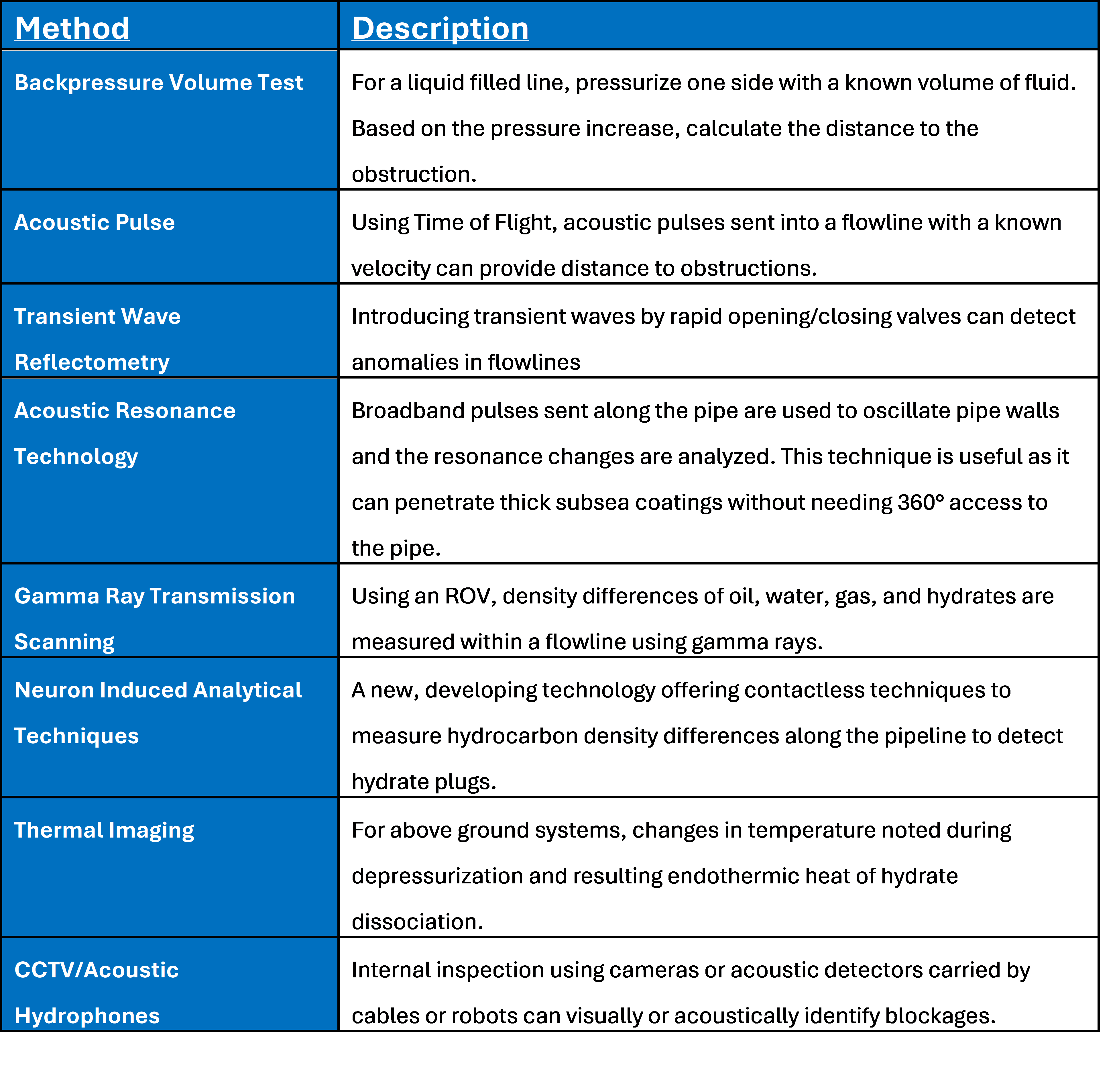
Subsea Hydrate Blockage Location Detection Technologies
How the hydrate plug is detected is very much down to the length of the line and whether you can easily access the outside of the pipeline. Accordingly, a topside pipeline is the easiest, whereas buried onshore and subsea pipelines are far more difficult.
It is also worth saying that no single plug locator method is perfect, a combination of approaches is often recommended to achieve precise results.
Recent advancements have introduced non-invasive tools specifically for deepwater flowlines where access is limited. The table below summarizes some of the available detection techniques.
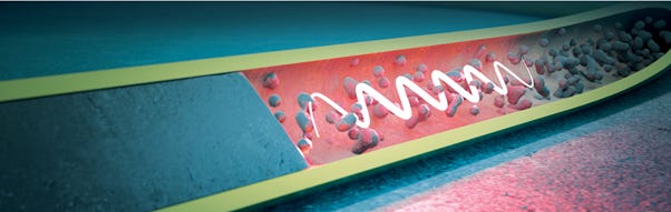
Acoustic Pulse Detection Method - Image courtesy of Find-Block® Paradigm Group
Pontem are in discussions with a supplier of one of the acoustic detection tools to combine our modelling expertise in the use of physics based models to predict hydrate plug locations.
Hydrate Blockage Remediation Techniques
There are several different techniques that can be used to remove hydrate blockages but the most commonly used are:
Thermodynamic Hydrate Inhibitor (THI) Injection
THI’s such as Methanol, MEG and TEG are used to melt the hydrate. Most facilities will have access to at least one of the chemicals, if not two.
THI’s work by altering the freeze point of hydrates forcing it to melt at the system pressure and temperature.
For a THI to work it must actually contact the hydrate plug, which is not always possible. There is almost always fluids between the plug and either end of the flow line, which makes THI placement a non-trivial exercise. Additionally, it is not recommended to use Methanol to melt a hydrate plug in a vertical pipe as Methanol will sit on top of the free water that is released as the hydrate starts melting due to it being lighter than water. This barrier stops the melting process.
Depressurization
If the injection of a THI has failed to remove the hydrate plug, the next option is to depressurize the pipeline to move the system outside the hydrate envelope. When it comes to depressurization there are two possible options:
Dual sided depressurization - The most common and preferred method used is two-sided depressurization because it minimizes the chance for a large pressure differences across the hydrate plug occurring, thus preventing the hydrate plug becoming a high velocity projectile.
Single sided depressurization - Usually not recommended as you run a greater risk of having a high pressure differential across the hydrate plug (i.e. >10 bar / 145 psi). However, there are instances where single sided depressurization has been used successfully but it needs to be done in a controlled manner and requires a thorough risk assessment before it is performed.
Impact of multiple plugs in a pipeline
In the case where multiple plugs have formed in the pipeline, extra caution needs to be taken even with two-sided depressurization. This is because in the case of multiple plugs, high pressure gas may still be trapped between two impermeable plugs so unbeknown to the operator there may be a significant dP across one of the plugs causing it to become a projectile if loosened due to the depressurization process.

Cooling during Depressurization
One of the draw backs of using depressurization to dissociate a hydrate plug is that sub-zero temperatures can be generated. This is manageable in uninsulated flowlines as the ambient temperatures warm up the system within hrs/days allowing the plugs to melt. However, many deepwater oilfields use highly insulated flowlines (e.g. U-values <10 W/m2K), which prevent the internally generated cold temperatures from being dissipated prolonging the hydrate dissociation process. This may mean that the ambient temperatures take weeks / months to move the system outside the hydrate region.
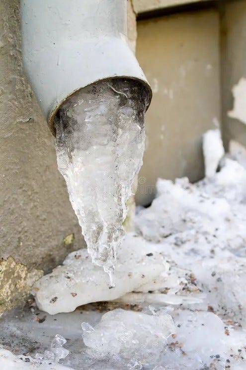
In flowlines that sit in sub-zero seawater temperatures this problem is exacerbated as it can lead to ice formation. This is a problem because no amount of depressurization will remove an ice plug. The only way to remove it is to somehow add some external heat to the pipeline, which we will talk about more later in this post.
All of this hopefully shows the complex thermodynamic process that occurs during hydrate plug dissociation and what needs to be evaluated upfront.
Use of heat to warm up the pipe
There are a number of heating options that have either been tried or proposed. These are:
The Petrobras SGN method
Subsea Active Electrical Heating
Electric Blankets and Heat tracing for topsides piping
Petrobras SGN Method
If you are a chemistry geek this one is for you. SGN stands for Self-Generated Nitrogen. SGN is a patented, thermo-chemical technique primarily used by the Brazilian National Oil company, Petrobras to remove hydrate and organic (paraffin) plugs in subsea flowlines, trees, and wells. This method relies on an exothermic redox reaction between two specialized, nitrogen-containing salt solutions (referred to as “C” and “N” solutions) in the presence of a catalyst to generate a high enough temperature to melt the hydrate plug. This is delivered via Coiled Tubing (CT)
Reaction: Ammonium chloride (NH4Cl) and sodium nitrite (NaNO2) react to produce nitrogen gas, sodium chloride, and water, releasing a significant amount of heat (∆H = -75kcal/mol).
Active Electrical Heating
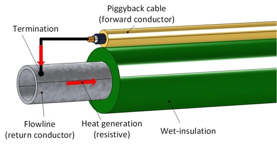
Direct Electrical Heating (DEH): This is the most commonly used active heating method, which uses the steel pipe as an electrical resistor to generate heat. An AC current is fed via a cable to the far end of the wet insulated pipeline, where it connects to the pipe, causing current to flow back through the steel, generating heat through both Joule and skin effects. This heat then passes from the metal pipe wall into the fluid in the pipe. A drawback of this method is that the heating process is not always uniform due to the resistive properties of each section of the pipe being slightly different.
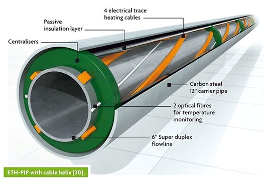
Electrically Trace Heated Pipe-in-Pipe (ETH-PiP): This works by using up to 3-phase trace heating cables strapped to the outside of the inner pipe of the P-i-P set-up and within the insulation layer of a flowline. Powered by subsea transformers, these cables generate heat via the Joule effect, which involves passing an electric current through the heat trace cables, generating heat that warms the inner production pipe and fluids to above the hydrate dissociation temperature. The copper cable achieves much better temperature control compared to DEH because the heat generated is consist throughout the length of the cable.
Subsea Hydrate Remediation Skids
When it comes to hydrate blockage removal, time is money because as long as the hydrate plug is there no production can happen. This is why the use of Active Electrical Heating is so useful. You can virtually flick a switch and the hydrate plug will start melting.
However not every field can afford active electrical heating and in a lot of instances the use of THI and/or depressurization just doesn’t work. This has driven the subsea service provider community to develop Hydrate Remediation Skids or Composite Coiled Tubing units, which attach to deepwater flow lines to help remove hydrate blockages quickly.
Hydrate Remediation Skids for System Depressurization
These are designed to connect to subsea manifolds and/or Production XTrees via a ROV to allow for quick dual sided depressurization of the system to <10bar and to inject THI into the system. Below are Hydrate Remediation Skids supplied by Subsea7 and Oceaneering that have been developed for this purpose. There are other providers of this type of skid as well.
Composite Coiled Tubing Units
There are a number of specialized coiled tubing technologies that use composite coiled tubing and specially designed heads to transport the coiled tubing along subsea pipelines. The lightweight and more flexible nature of the composite tubing allows the technology to do things the traditional stainless steel coil tubing can’t. Like reaching up to 20kms along subsea pipelines and being able to navigate through multiple 5D bends.
The composite coiled tubing can be inserted directly into the outlet of the subsea riser on the topsides process or via multiple subsea intervention access points (i.e. 2” ‘hot-stab’s) on subsea equipment. After insertion, the coiled tubing can be used in multiple ways to remediate hydrates. These are:
To dose THI directly onto the hydrate blockage. The coiled tubing is fed down the riser or via the intervention points in the subsea equipment to the immediate vicinity of the blockage and THI is injected directly onto the hydrate.
To inject hot fluids (e.g. diesel) directly onto the hydrate formation for thermal dissociation using the same methods described above.
To inject gas to the base of the riser to unload the liquids, and remove the subsequent static head, from the system, attaining hydrate free pressures subsea. This is only required if the system cannot be depressurized via the usual flare path due to high liquid hold-up in the riser.
Hydrate Remediation Successes
As with everything it is important to know that there are effective solutions out there with respect to getting rid of hydrates. Below is a small list of successful cases where hydrate blockages were remediated successfully.
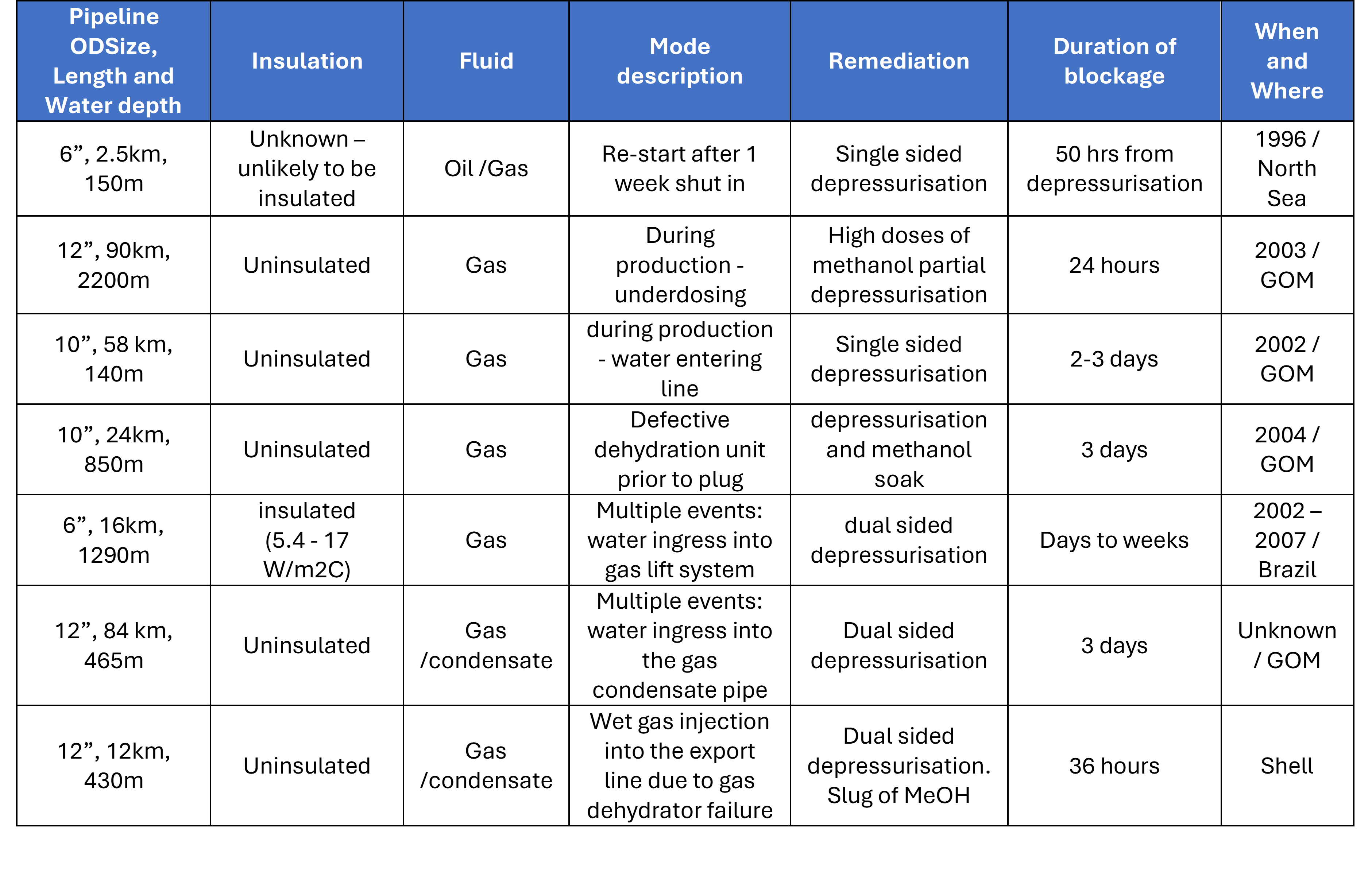
The above data demonstrates that most recorded hydrate remediation cases are gas or gas condensate systems and that the majority of the blockages occurred due to mal-operation or failure of the chemical injection and/or gas dehydration systems. Furthermore for uninsulated lines, hydrate plug removal took hours / days but for the only insulated line case included, hydrate plug removal increased to days / weeks. This corroborates the description previously supplied regarding what happens when trying to dissociate a hydrate plug in an insulated line.
The Hydrate Plug is gone so what to do next
Finally, there is no point in successfully removing the hydrate blockage without preparing the system properly for restart. Otherwise, you will probably just re-block the line.

To get the system up and running again Pontem recommend the following:
Remove the uninhibited water that caused the hydrate plug in the first place. This can be done by running a low-pressure pig at this point to remove the uninhibited fluids.
If you can’t run a pig, flood the system with as much Methanol or MEG as possible, with one eye on the costs and the other on how the aqueous phase will be disposed off once it comes out of the pipeline.
Once you think you have eliminated/inhibited the water in the line, make sure the chemical injection system or gas dehydration system is back up and running.
For the systems that normally operate outside the hydrate region during steady state flow, it is recommended to restart the system at as low a pressure as possible after dosing with Methanol or MEG until the flowing temperatures are above the hydrate dissociation temperature.
If you follow those points you will give yourself every chance to get your system up and running again but unfortunately there are never any guarantees in this game.
We hope this post has improved your understanding of the Hydrate Remediation process and as ever there is always more to these things than you think. It is not until you experience having to do this that the gravity of the process sinks in. This is where Pontem can help because we have that experience and are more than happy to share it so don’t be shy, contact us.